to close
to close
Many of the years that the authors have been involved with FRC, we wanted to collect I/O on the Driver Station. Sometimes it was an abort button, other times a potentiometer to select an auto program, and still others we wanted to put LED’s on the Driver Station that would light up to alert the drivers/coach to something (game piece acquired, aligned for shot, etc.)
The TI Launchpad allows for the input to the driverstation by acting as an extra Joystick but requires a bit of setup and is only an input.
Below is presented a setup that allows for an Arduino to be used for generic I/O on the Driver Station through the LabVIEW Interface for Arduino (now, LINX).
For this tutorial, we will implement reading a potentiometer and displaying it on the Dashboard. The setup presented below can be used to read or write to/from any of the pins on the Arduino (including writing PWM out).
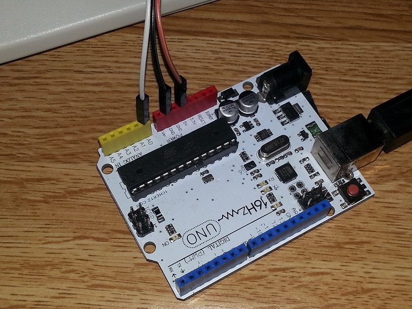
First, we wire a potentiometer so that it can act as an Analog Input to the Arduino.
We wire 5V and Ground from the Arduino to the two outer pins of the potentiometer and connect the wiper pin to A0.
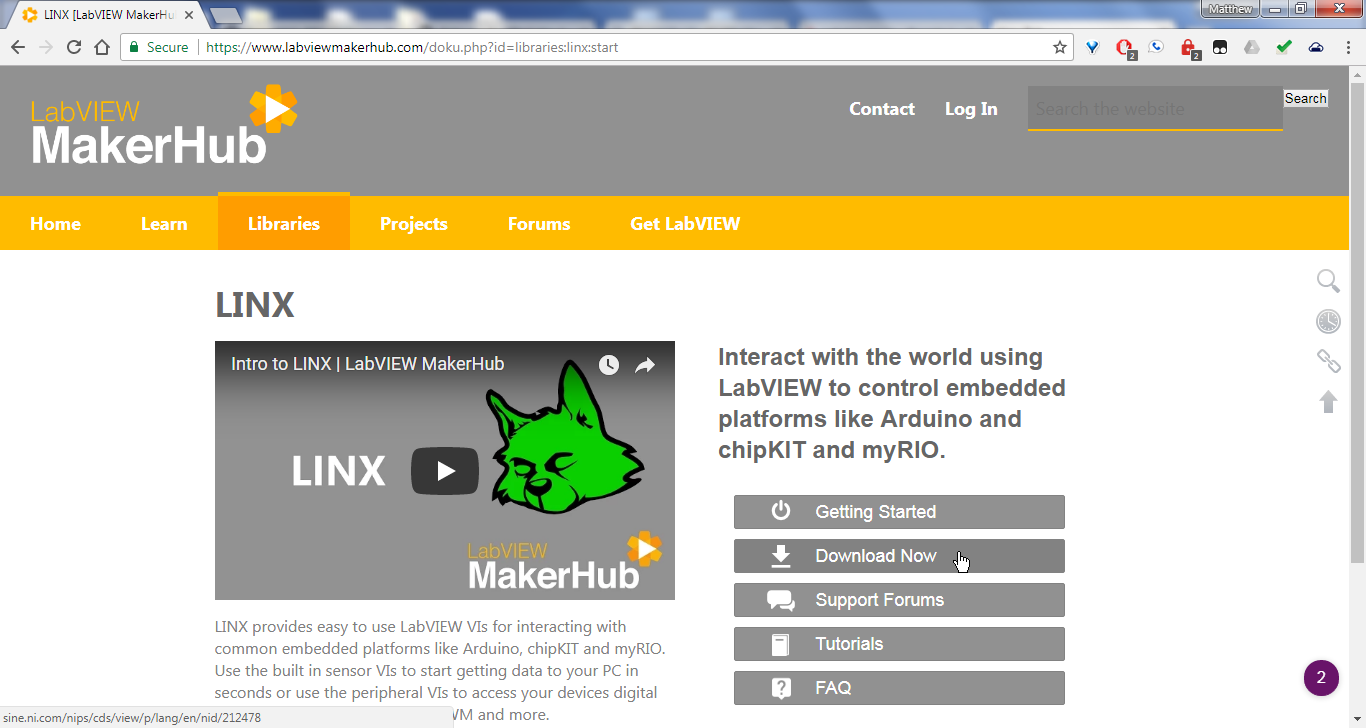
The library we will use to interact with the Arduino from LabVIEW is called the LabVIEW Interface for Arduino (now, LINX) which we need to download and install to LabVIEW.
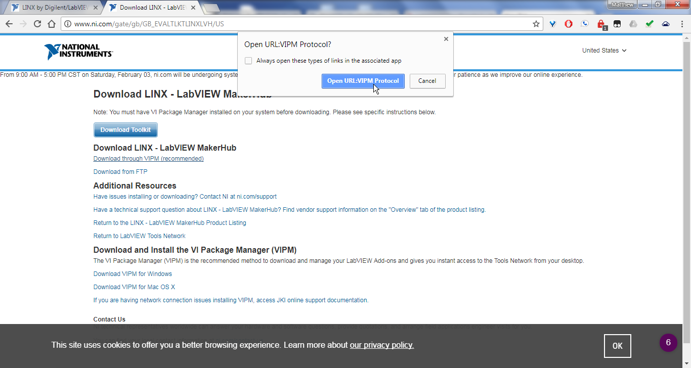
If prompted, select to open in Package Manager.
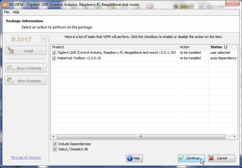
Select Install
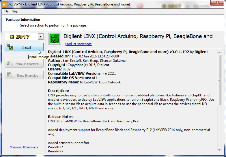
Follow prompts
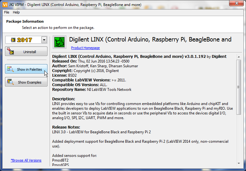
To see where the installed library is in the palette, select ‘Show in Palettes’
Connect the Arduino to the computer and open LabVIEW (Note: The Arduino driver is needed for this step - you can download and install it with the default IDE at Arduino.cc)
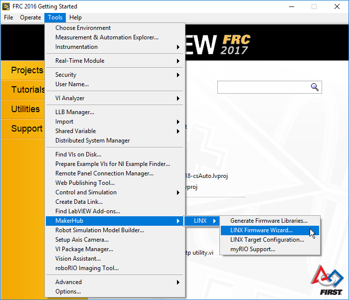
From the launch screen (or any screen actually) select Tools -> MakerHub -> LINX -> LINX Firmware Wizard…
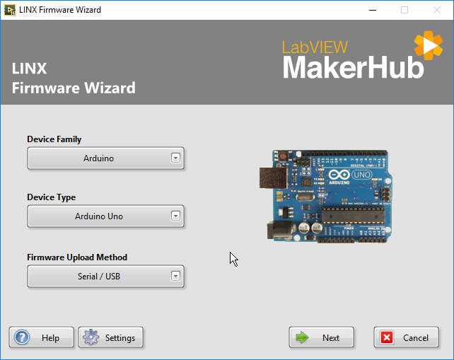
Select the correct type of Arduino firmware to use and click next.
Select the port that the Arduino is connected to (See Arduino getting started info for help) and click next to download firmware.
This firmware implements a communication interface that allows for the VIs we installed earlier to control the I/O on the Arduino.
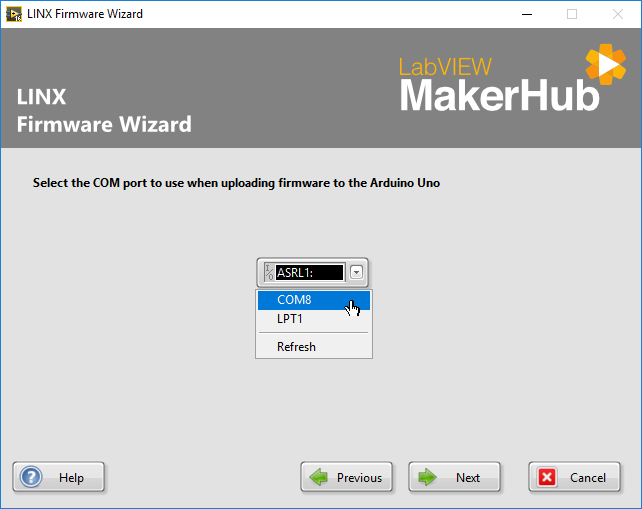
Click next to download the default firmware image
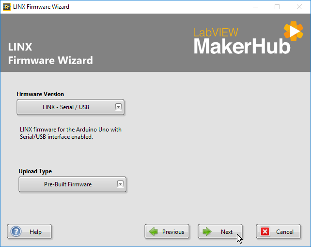
Once the download finishes, press “Finish” to return to the LabVIEW welcome screen.
Select a New -> FRC Dashboard Project.
In the configuration dialogue choose what you would like to name the project and where to save it and click next.
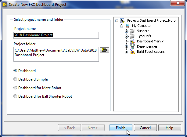
In the Project Explorer window, select and open “Dashboard Main.vi”
This is a source code version of the default dashboard. Go to the block diagram (press CTRL + e or select Window -> Show Block Diagram).
Scroll to the top (the region that is expected to be edited), and add a While Loop.
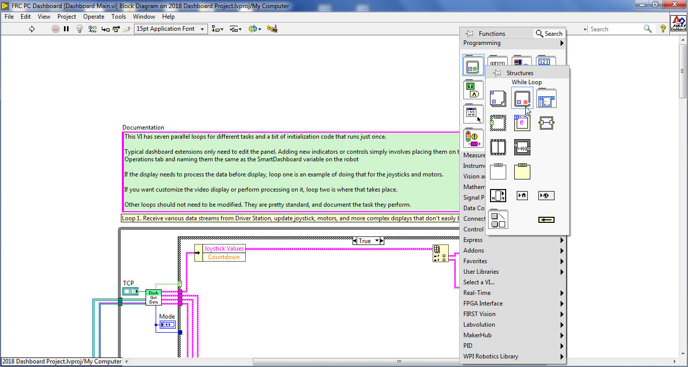
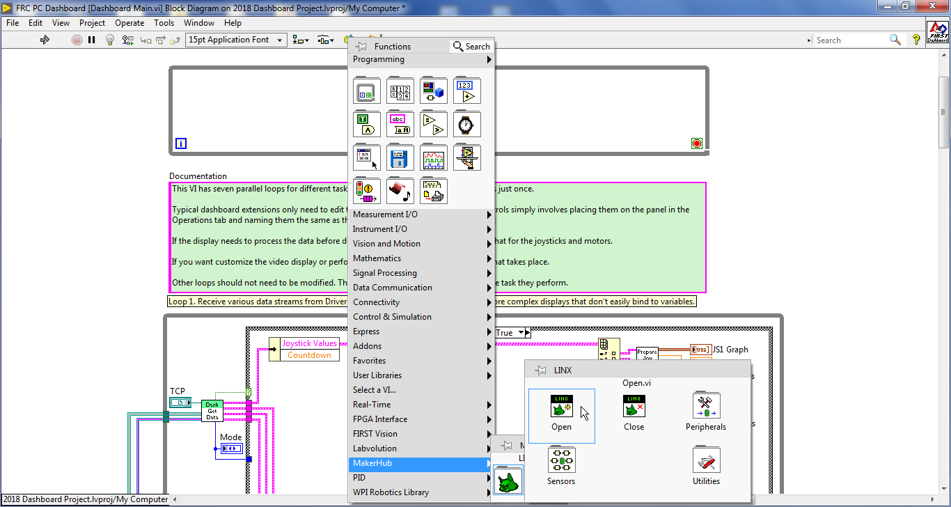
Open the palette (right click if it is not already open) and select MakerHub -> LINX -> Open
This VI creates the communication link to the Arduino for us.
Place it to the left of the new While Loop
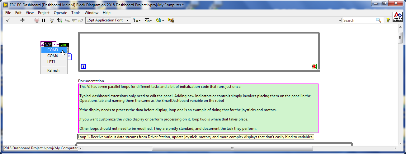
Right click on the top left terminal of the Open.vi and select Create -> Constant
Select the port the Arduino is connected to.
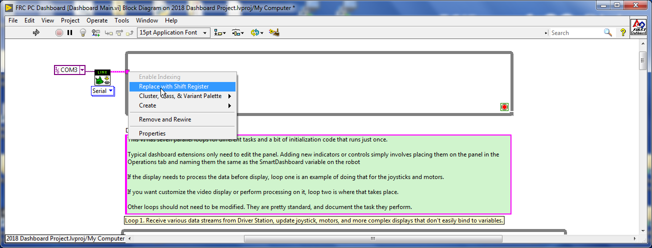
Wire the top right terminal (LINX Resource) to the While Loop and set it to a Shift Register
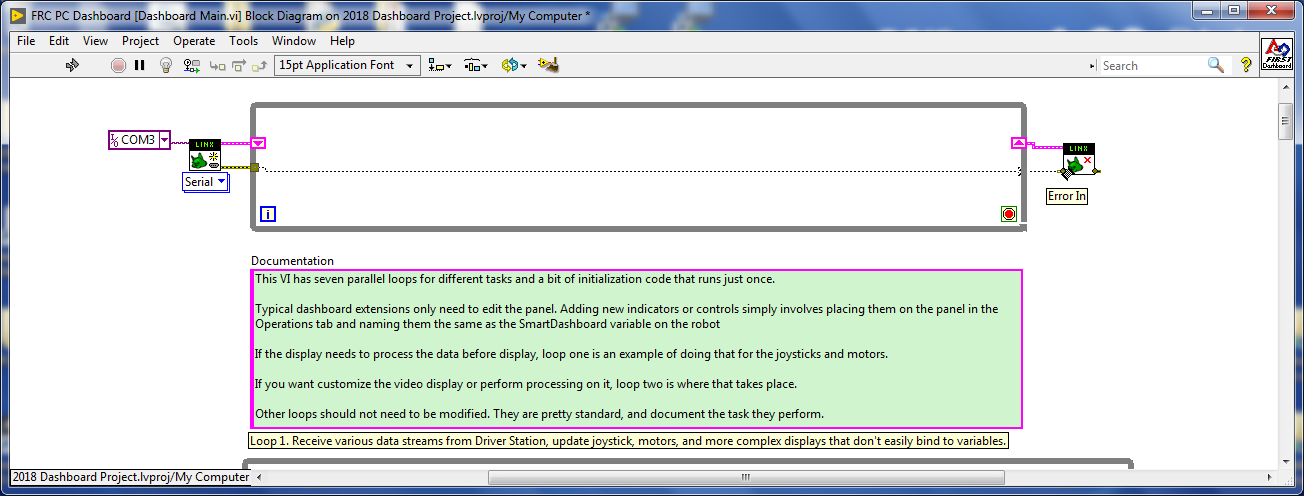
Wire the error out from the Open to the While Loop.
Get a Close.vi from the LINX palette and place it to the right of the while Loop - this VI will unreserve the port.
Wire the error from the left of the While Loop to the close vi
Branch the error wire and connect it to the stop terminal for the loop.
From the MakerHub -> LINX -> Peripherals -> Analog palette Select the Analog Read.vi
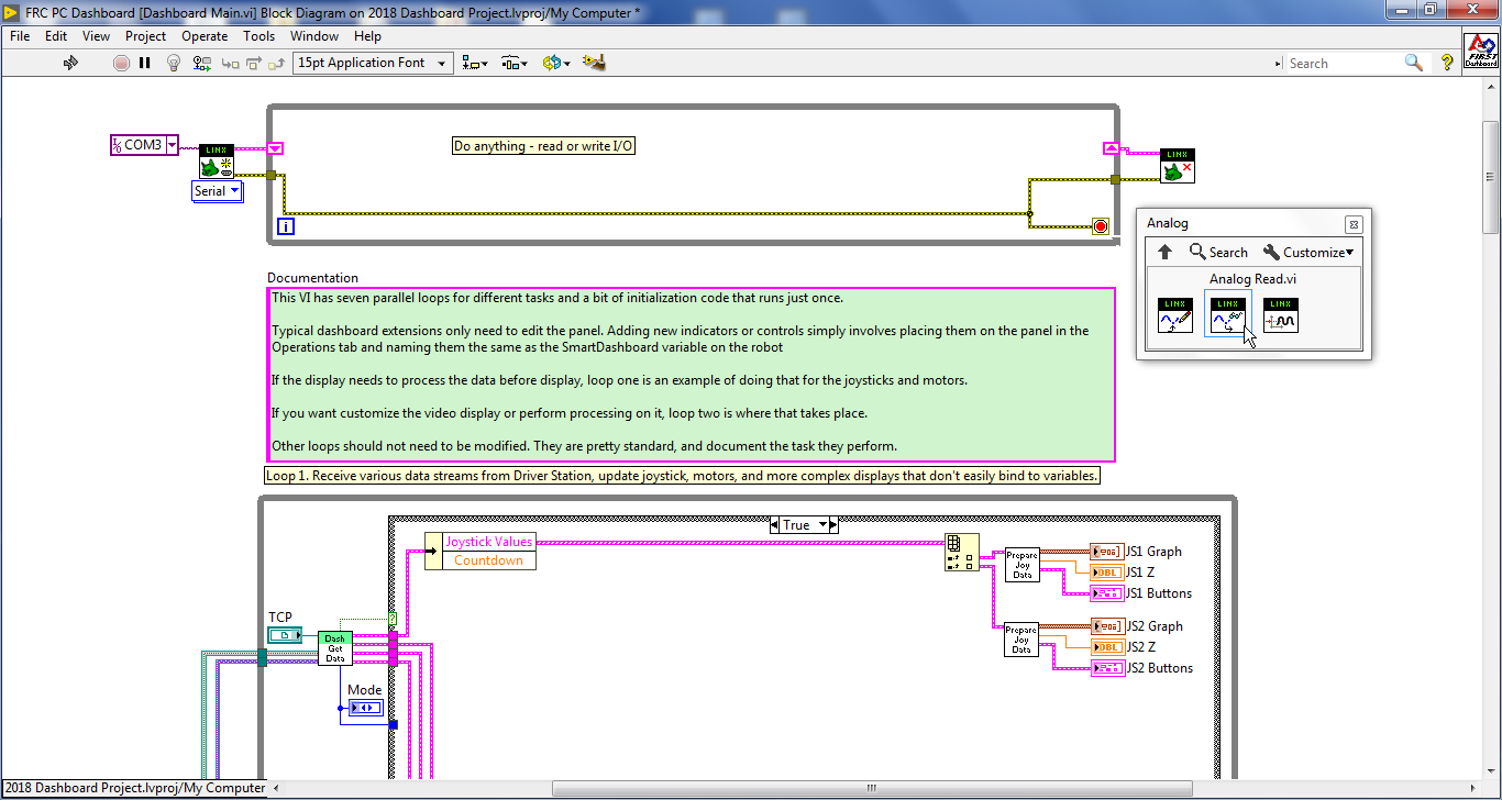
And set the Analog channel and pass the reference and the error through the read vi
Unfortunately, if we abort the VI, the port to the Arduino is not properly closed.
The port will remain reserved (but unavailable to the Open.vi) until the owning process (right now, LabVIEW) is completely shut down.
This does not create an issue for the built version of the dashboard as that is an executable of its own and releases the port when it is closed.
To make this easier to deal with while in development in LabVIEW, we will create a stop button in a new VI. Create a new VI.
Place a stop button and an round LED (or some other form of both a Boolean control and indicator) on the front panel.
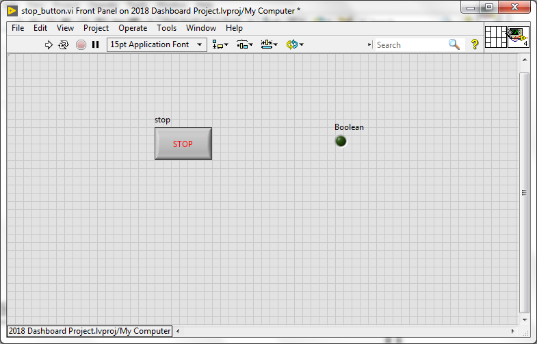
Connect the output to a terminal on the VI by clicking on the terminal first, then the indicator
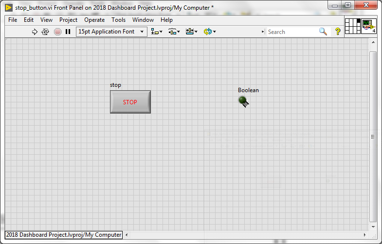
On the block diagram, simply connect the control to the indicator.
This will allow you to press the button to send a True out to the calling VI.
Save this vi as stop_button.vi
Drag the VI just created (by the icon) to the block diagram of the Dashboard Main.vi
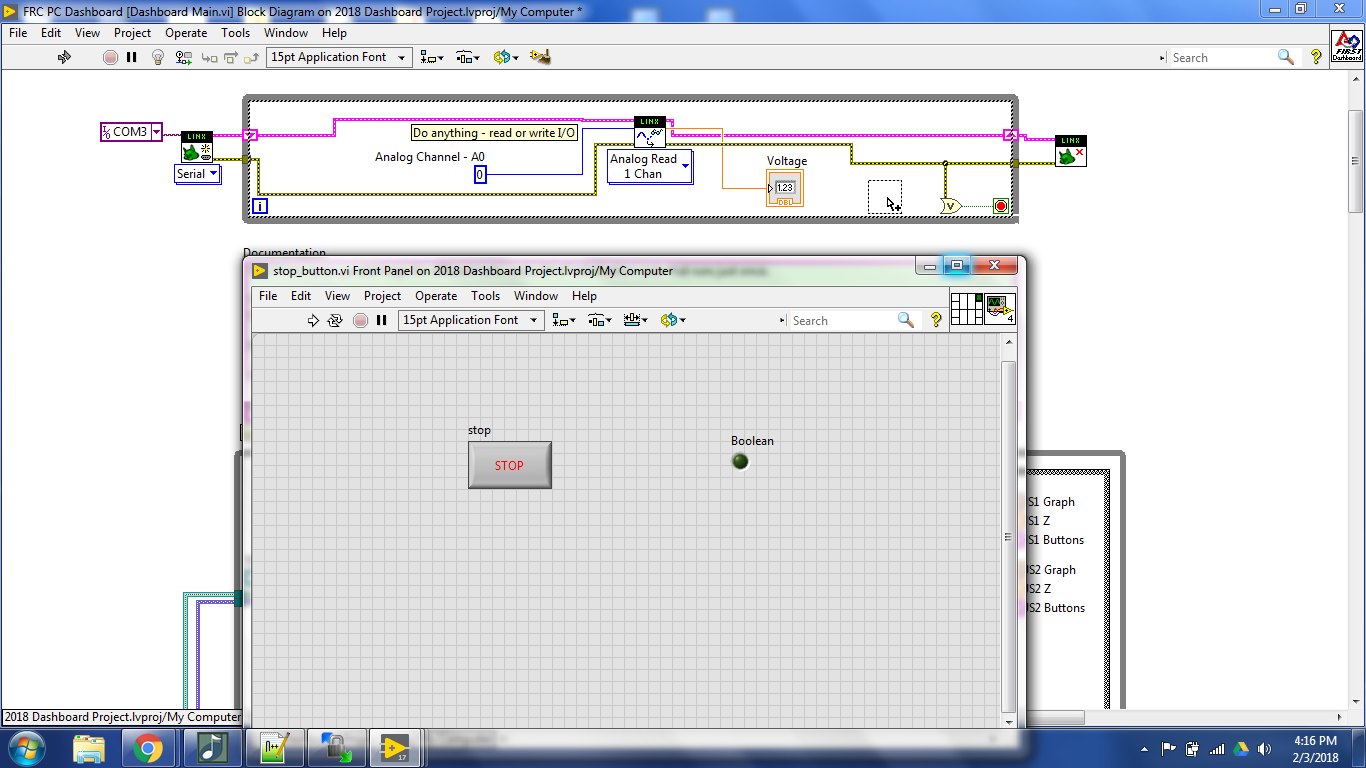
Insert an OR on the Error wire going to the stop terminal and connect the output of the Stop VI to the OR
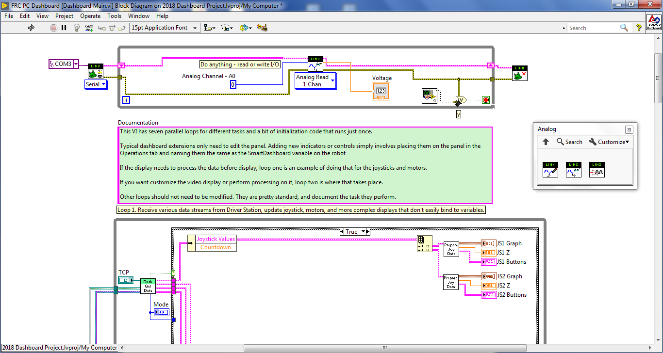
The finished product
For the sake of testing it, we will replace the numeric indicator with a Horizontal Progress bar.
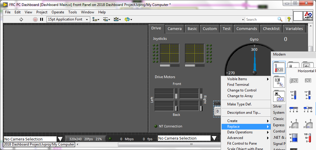
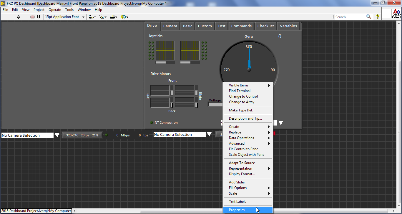
Open Properties on the bar.
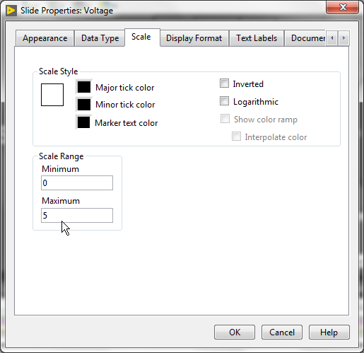
On the scale tab set the Maximum to 5 (the Arduino will read an AI from 0V to 5V).
Run the Dashboard VI. After a few seconds, the connection with the Arduino will be established and the progress bar will update as you move the potentiometer.
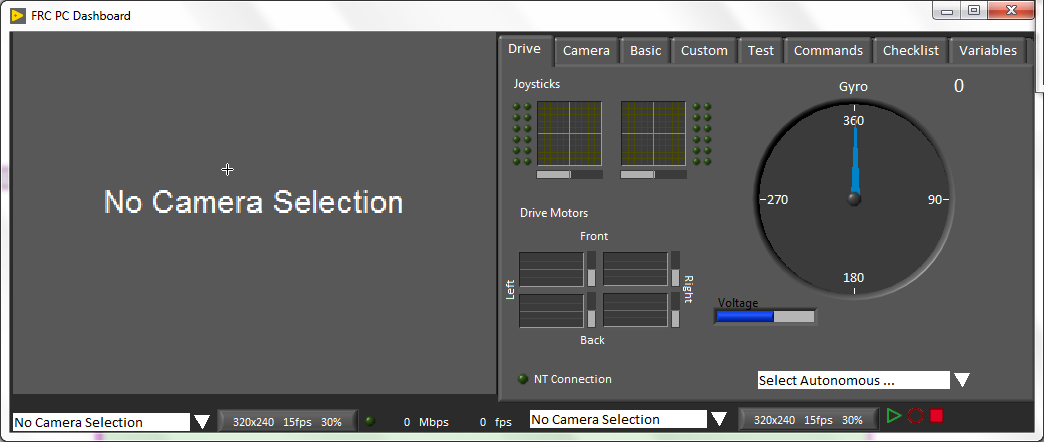
To stop running, first open stop_button.vi and press the stop button the front panel
This will cause the Arduino loop to stop executing allowing the Close.vi to close the port to it.
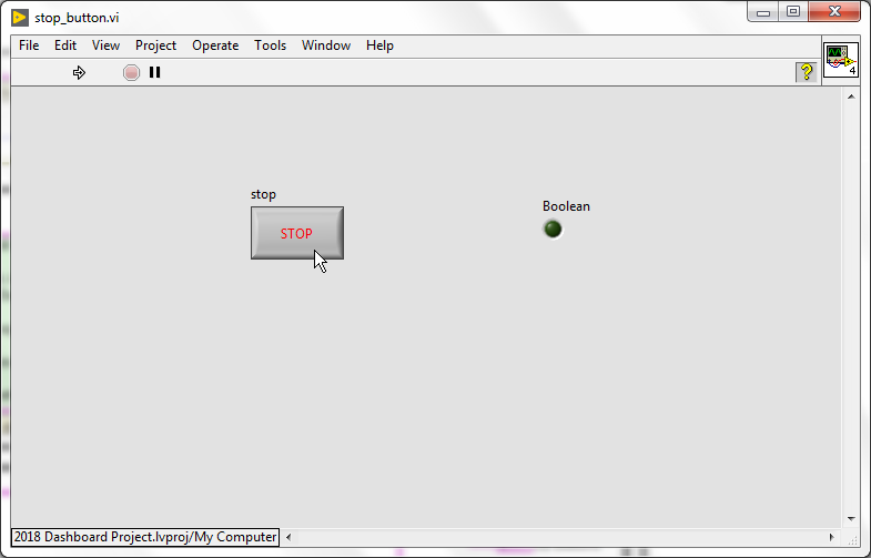
(How can I know if it worked?, the stop_button vi will stop executing because it is no longer getting called).
You can then abort the dashboard VI from the block diagram.
See our tutorial on Connecting a Gyro to the dashboard for more information on using this custom dashboard with the Driver Station and running it.
To send this value to the robot, use the Dashboard Write vi and name the variable.
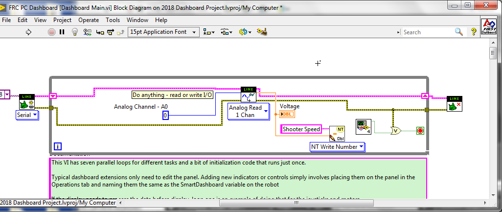
The Dashboard VI’s can be used to write data on the robot and read it on the dashboard, or vice versa.
Use the write vi to send the data and the read vi to receive it. Make sure to use the same data type on each end and the same (case-sensitive) name.
You can use the data sent from the robot to control the Arduino as well.
Easiest way, build it, open it, then open the Driver Station. The DS should recognize that a dashboard is already open and just work with it.
Google Form to request details